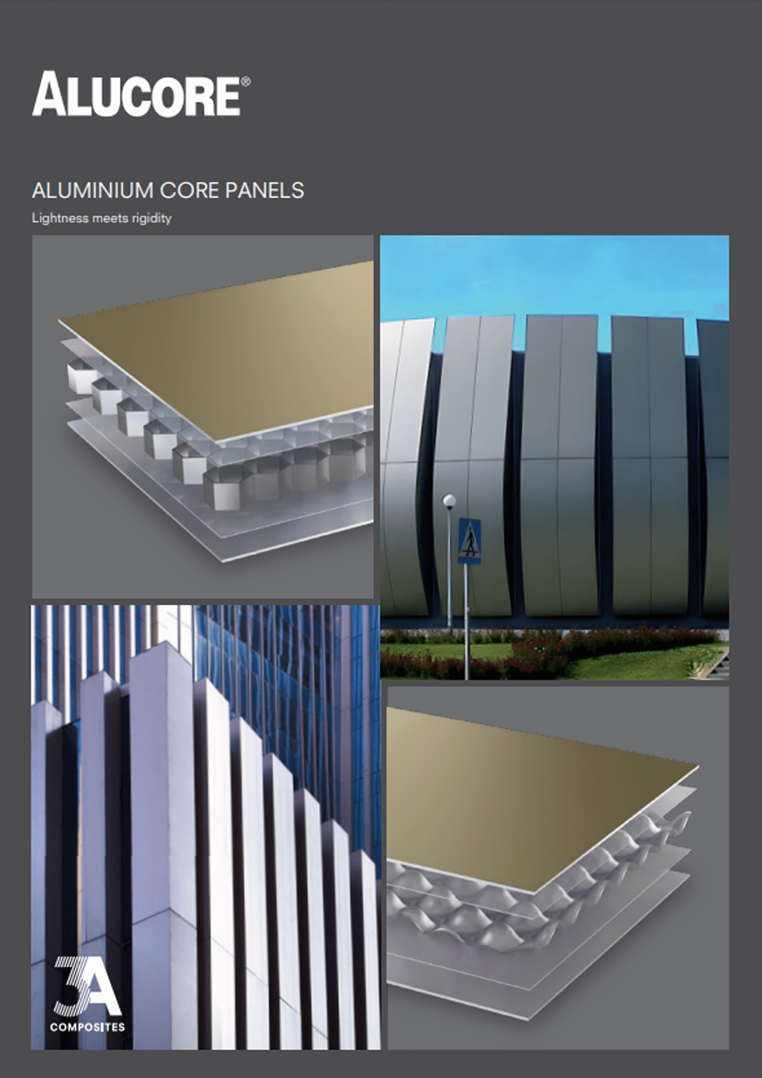
Aluminium Honeycomb & ACCP Panels
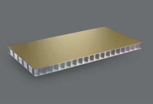
ALUCORE® is an innovative aluminium composite panel consisting of two aluminium cover sheets and a core of aluminium.
ALUCORE® comes in 2 variants – ALUCORE® ACCP and ALUCORE® Honeycomb panels. ALUCORE® features marine-grade corrosion-resistant alloy 5005 H24 for durability. The PVDF/FEVE coating, as per AAMA 2605, ensures long-term performance and protection from UV radiation and weathering.


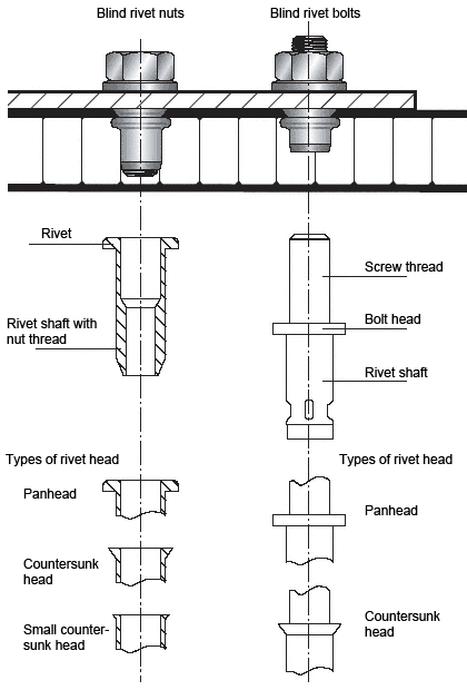
Rivets – not penetrating the panel
Rivets generally must be anchored in the 1mm thick ALUCORE® cover sheets. Sections can be attached to ALUCORE® with commercially available rivets for aluminium constructions. After drilling a blind hole of the same diameter as the rivet shank, the rivets can be anchored in the cover sheet. As a rule, rivets with stainless steel mandrel are used.For outdoor use please note:
- For outdoor use aluminium blind rivets that have been approved for construction with a 5 mm shaft diameter and an attachment head diameter of 11 or 14 mm are used.
- Please take the thermal expansion of the panel into account (2.4 mm/m/100°C). To avoid jamming, the hole in the panel must be large enough to allow for expansion.
- With the shaft of the rivet fitting closely to the edge of the hole, the attachment head must cover over 1 mm of the area surrounding the hole.
- Multi-step drills or sleeves having corresponding diameters are used for centrically drilling holes into the panel and the substructure and for centrically fitting the rivet.
- Rivet attachment jigs are used for fitting blind rivets without jamming allowing for a tolerance of 0.3 mm. Make sure to use rivet attachment jigs and rivets from the same manufacturer, as the height of the attachment head according to DIN 7337 may vary.
- The clamping thickness results from the thickness of the material to be riveted plus an additional value of 2 mm to ensure that the closing head is perfectly formed. In accordance with this clamping thickness the corresponding shaft length is determined in the tables provided by the rivet manufacturers.
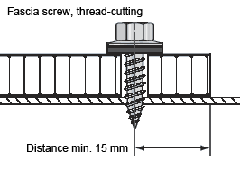
Threaded fasteners for outdoor use
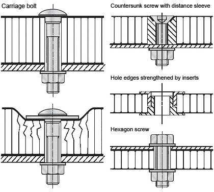
For outdoor use make sure to take the thermal expansion of the panel into account. To avoid jamming, the hole diameter in the panel must allow for the expansion. Fastening without jamming is possible using fascia screws made of stainless steel with sealing washer (Fig. 1) that have been approved for construction. The screws must be suitable for the corresponding substructure (please note the information given by the manufacturer). The screws should be tightened with a torque wrench or screwdriver so that the sealing washer is placed on the panel for sealing the bore hole without exerting pressure to the panel. Multi-step drills or sleeves having corresponding diameters are used for centrically drilling holes into the panel and the substructure and for centrically fitting the rivet. Important: Make sure to remove the protective foil prior to screwing.Examples for threaded fasteners
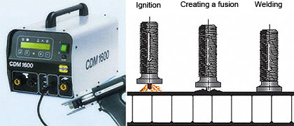
 Stud welding with tip ignition on mill-finished ALUCORE® surfaces
Process:
- The capacitor battery is charged.
- A spring in the welding gun moves the stud (with tip) towards the work-piece.
- The tip comes into contact with the work-piece and thereby closes the circuit. The rapidly increasing current causes the ignition tip to melt instantaneously, thus initiating the electric arc.
- Stud and work-piece are welded together.
- When the stud touches the work-piece the electric arc is extinguished, the fusion zones on stud and work-piece are joined and solidify.
Frequently Asked Questions about ALUCORE®
What is ALUCORE®?
ALUCORE® is a premium aluminium composite panel that uses an advanced aluminium honeycomb core instead of conventional fillers. These aluminium honeycomb panels are known for their high strength, lightweight structure, and long-term durability. They are ideal for architectural facade, transport, marine, and industrial projects where both performance and aesthetics are crucial.
What makes ALUCORE® different from traditional aluminium composite panels?
Unlike standard ACPs that use polyethene or mineral cores, ALUCORE® incorporates a bonded aluminium honeycomb sheet as its core. This design drastically reduces weight while significantly improving rigidity, impact resistance, and dimensional stability. The result is aluminium honeycomb panels that provide superior durability, fire safety, and structural reliability compared to conventional ACPs.
What are the available variants of ALUCORE®?
ALUCORE® is available in two main variants: ALUCORE® ACCP Panels (for architectural cladding and façade systems) and ALUCORE® Honeycomb Panels. In construction, aluminium honeycomb panels are preferred for facades, roofing, ceilings, canopies, and interior partitions because of their high load-bearing capacity, excellent dimensional stability, fire resistance, and lightweight structure. These properties ensure long-term durability and reduced structural load without compromising on aesthetics.
What is the significance of the marine-grade corrosion-resistant alloy 5005 H24?
ALUCORE® uses marine-grade alloy 5005 H24 in its aluminium honeycomb panels. This alloy provides outstanding corrosion resistance, making the panels highly reliable in humid, coastal, and industrial environments. It prevents rust and degradation while preserving structural integrity and aesthetic finish over the years.
What is the difference between ALUCORE® ACCP and ALUCORE® Honeycomb?
ALUCORE® ACCP Panels are designed for exterior cladding and facade applications, delivering durability and modern aesthetics. On the other hand, ALUCORE® aluminium honeycomb panels are ideal for construction projects that demand lightweight yet highly rigid materials, making them perfect for roofing, canopies, ceilings, and architectural facades where strength and long-term performance are essential.
Where can ALUCORE® panels be used?
ALUCORE® aluminium honeycomb panels are highly versatile. They can be used in architectural facades, roofing systems, canopies, ceilings, and cladding applications. With their strength, lightweight structure, and long-term durability, aluminium honeycomb panels are an ideal choice for modern construction projects requiring both performance and aesthetics.
Is ALUCORE® fire-resistant?
Yes, ALUCORE® is fire resistant because of the aluminium honeycomb core; they do not contain combustible fillers found in traditional ACPs. This makes honeycomb panels compliant with fire safety standards and a safe choice for high-rise buildings, public spaces, and transport projects.
Can ALUCORE® panels be customized in terms of size, colour, and finish?
Absolutely. ALUCORE® aluminium honeycomb panels can be customized to meet specific project needs. Options include tailored sizes, metallic tones, wood or stone finishes, and various surface textures. This flexibility allows architects to achieve the desired performance and look.
Does ALUCORE® meet international quality and safety standards?
Yes. ALUCORE® aluminium honeycomb panels are tested for fire resistance, weather durability, and mechanical strength. They meet globally recognized standards and building codes, ensuring long-term performance and safety trusted by architects and engineers worldwide.
What coating is applied to ALUCORE® for protection?
ALUCORE® panels are protected with high-quality PVDF or FEVE coatings. These finishes enhance resistance against UV rays, weathering, chemicals, and pollution. They also ensure long-term colour stability and a durable surface finish, making aluminium honeycomb sheets look visually appealing for decades.
